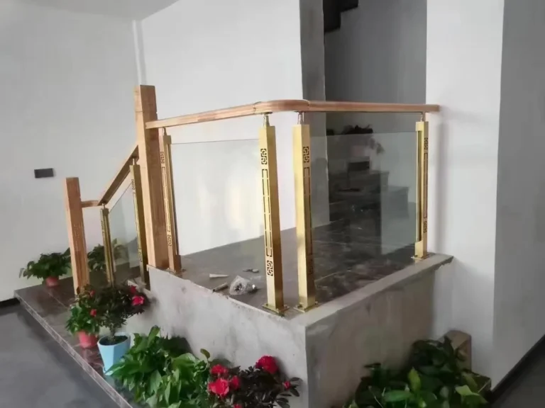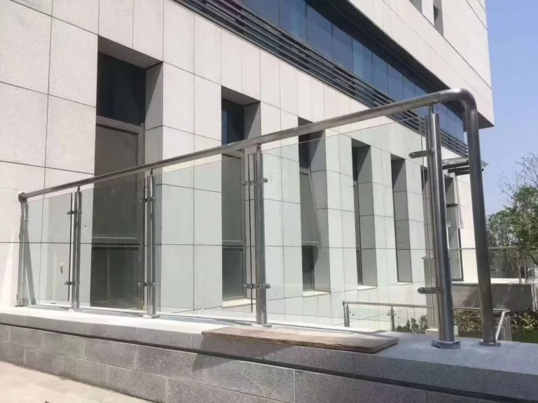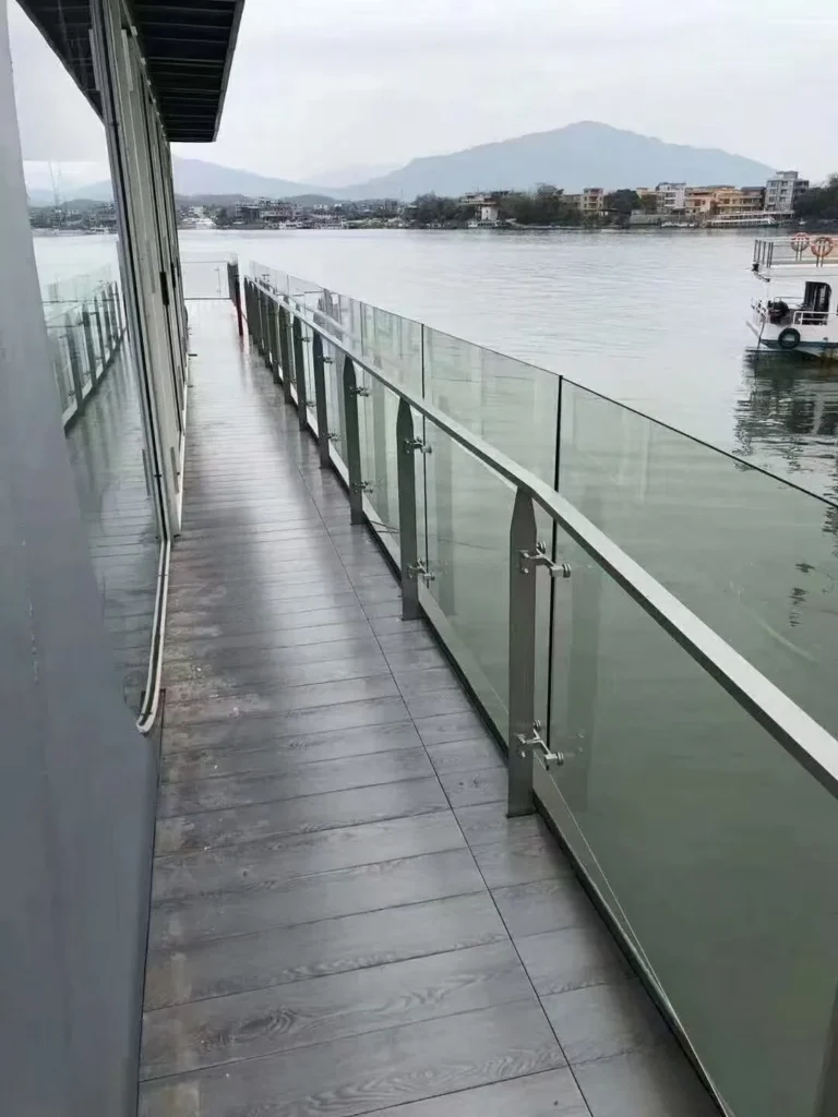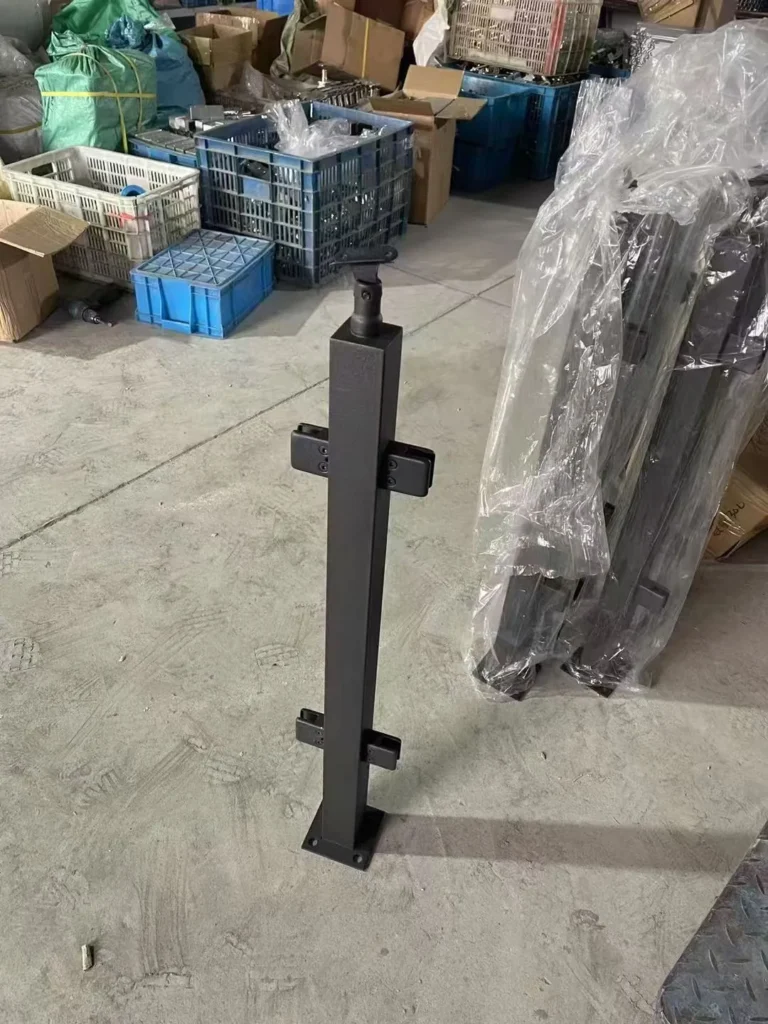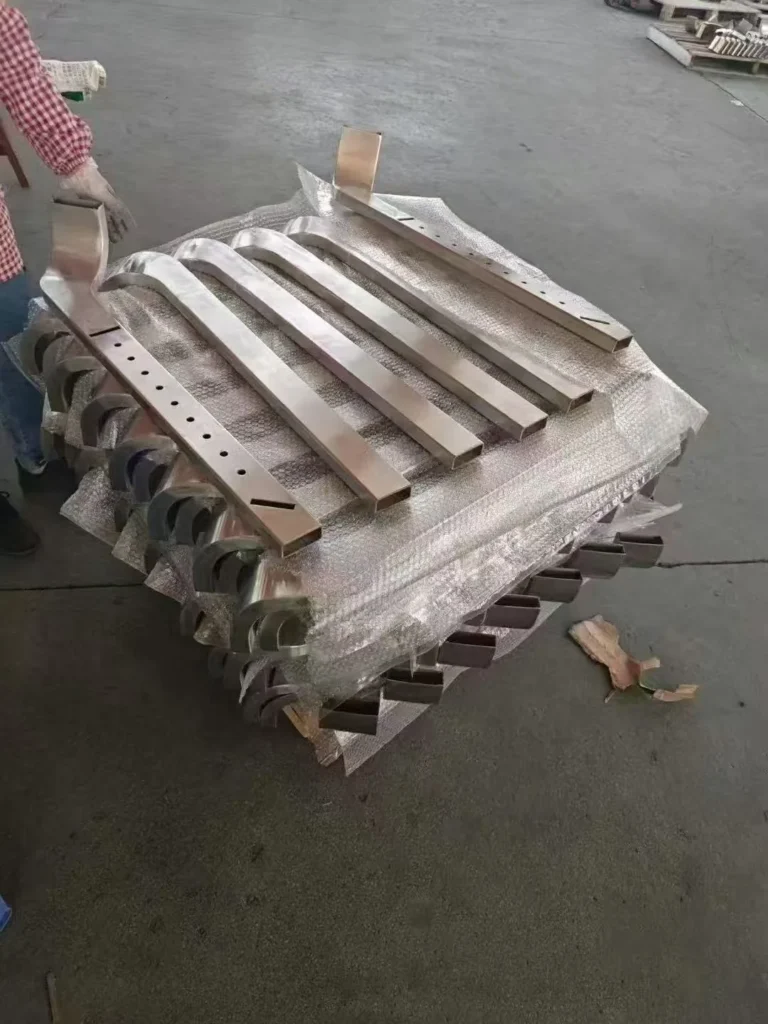
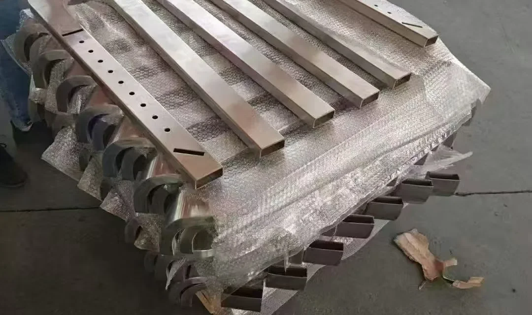
Lay out the gripping path at the stair landing before placing the stainless steel posts that support it. Show where the rail changes slope, how it returns or continues, and which brackets support each segment. Cross-check those positions against the glass and the required clear space. One sloped elevation rarely resolves the geometry where a flight meets a landing.
Draw the rail path beyond the last step
Mark the finished stair nosings and landing elevations. Trace the top of the gripping surface through the slope change and to the return or adjacent run. The U.S. Access Board stairway guidance explains continuity and extension requirements for applicable U.S. projects. Ask the project designer which rules apply, including exceptions, before translating the rail path into post dimensions.
Separate the rail path from the support locations
| Drawing feature | Show together | Release check |
|---|---|---|
| Change of slope | Nosing, landing and rail path | Compare to approved geometry |
| Rail return or turn | Plan, elevation and grip zone | Review actual clearance |
| Support bracket | Post center and fitting orientation | Check with glass installed |
| Site revision | Finished levels and affected locations | Confirm both shop packages |
The start of a bend, the rail splice and the center of a post do not need to share one station. An offset bracket may put the support under the correct part of the rail, provided its configuration is approved and leaves the required space. Use both a plan and a section to show the actual assembled relationship.
Reconcile glass fabrication and bracket access
Identify if the same landing post also carries a glass clamp. Compare each fastener and cover with the fitting positions and the intended gripping area. Check access for installing and removing the bracket at the actual orientation. Where a nearby wall or glass panel restricts access, mark the installation sequence and avoid relying on a view of the bare post.
Example: the two rail elevations look correct by themselves
A sloped rail meets a level segment on a turn. The separate elevations look correct, but the plan shows a bracket leg crossing the intended gripping path. The buyer asks the detailer to revise the support and show the turn as a single assembly. The new drawing is compared with the glass schedule, so the updated support does not trigger an unplanned hole or clamp change.
Give each variant a separate release reference
For each transition location record the station, hand, support type, bracket orientation and rail detail number. Check the elevation and clearances in a mock-up using the actual components where required. Mark the accepted variant on order and packing records so the landing support is not sent to an intermediate stair position.
What if the site floor level changes?
Measure from the current approved finished surface references and raise the discrepancy. Review the effect on the handrail path, bracket and glass before ordering revised posts.
Use the related procurement guide alongside the stair glass balustrade post system. Send the released drawing and relevant check records for a project quotation.