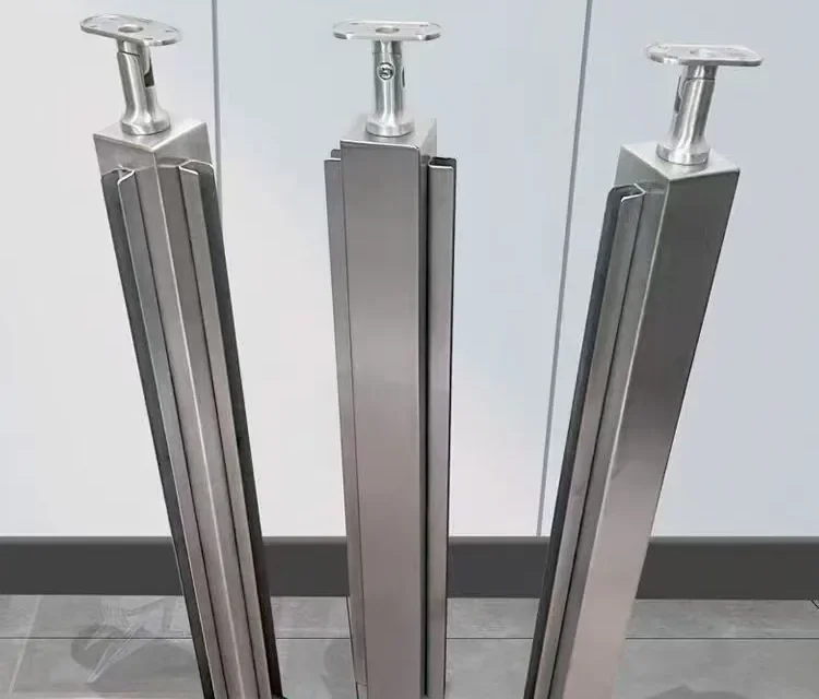
Short answer: a stainless steel railing post drawing should define functional datums first, then locate base-plate holes, glass fittings, handrail supports and visible surfaces from those references. Tolerances must protect fit, alignment and inspection without being tighter than the process needs. Never rely on one blanket tolerance: state the governing drawing standard, critical characteristics, measurement method, revision and acceptance stage.
Why railing post drawings fail even when every dimension is present
A drawing can contain many dimensions and still leave the manufacturer guessing. Common gaps include no stable datum, chained dimensions that accumulate variation, unclear left/right orientation, unspecified hole-centre relationships, conflicting 2D and 3D files, and no definition of when or how the finished part will be measured.
The goal is to connect each important feature to the surface, axis or plane controlling installation and its glass, handrail and substrate interfaces.
What is a datum on a stainless steel railing post drawing?
A datum is an exact reference used to establish location or orientation. A datum feature is the real surface or feature on the manufactured post from which that reference is derived. The distinction matters because an actual base plate, tube face or hole has manufacturing variation.
ISO 5459:2024 specifies terminology, rules and methodology for indicating and understanding datums and datum systems in technical product documentation. The selected datum system should represent the way the post is functionally located, not simply the easiest edge to dimension in CAD.
A practical datum strategy for railing posts
The following is an illustration, not a universal prescription. A top-mounted square post might use the base mounting face as primary reference and two perpendicular post centre planes as secondary and tertiary references. A fascia or stair post may need another system.
| Functional feature | Possible reference logic | Question to resolve |
|---|---|---|
| Base mounting face | Primary plane establishing seating | Is the part checked before or after any cover, shim or gasket? |
| Post centre planes or axis | Controls post location relative to the base | Is the post centred or intentionally offset? |
| Anchor holes or slots | Located from the installation datum system | Which pattern matches the approved anchors and substrate? |
| Glass clamps or adapters | Located from base and post references | Are centres controlled individually or as a pattern? |
| Handrail support | Height and orientation from installation references | Is the support straight, angled, handed or adjustable? |
| Visible finish faces | Identified independently from geometry | Which faces and grain directions are architecturally critical? |
For round posts, an axis may be more useful than two centre planes, but asymmetric fittings still need rotational orientation. For flat-bar posts, the broad face often controls appearance and glass alignment. Review the railing post types guide before applying one strategy to every shape.
Why baseline dimensions are safer than long dimension chains
A chain locates each feature from the previous feature. Variation can therefore accumulate along the chain. Baseline or coordinate dimensions locate related features from a common origin, making functional relationships and inspection easier to understand.
For a row of glass adapters, define whether each centre is controlled from the base, by adjacent spacing, or both. Avoid conflicting duplicate dimensions and state what governs if CAD and drawing disagree.
The same applies to anchor holes. Plate edges may locate a pattern when they are controlled and functional; a surveyed post centreline may require another reference.
How should hole centres and patterns be specified?
State hole quantity, size, shape and centre locations. For slots, show length, width and direction. Identify counterbores, countersinks or threaded features separately, including the required side of the part. A photograph or generic product code is not sufficient.
Control the pattern in the way it functions. A glass-adapter pattern may need location relative to the base, mutual spacing and orientation to a visible post face. An anchor-hole pattern must match the approved connection and installation access. Slots should not be added merely to conceal uncertain site dimensions; any change to the connection geometry requires the appropriate design review.
Which geometrical controls may matter?
Size tolerances alone do not fully control form, orientation or location. Depending on the design, relevant characteristics may include base-plate flatness, post perpendicularity, position of hole patterns, orientation of handrail supports, profile of curved blades or runout of round components.
ISO 1101:2017 defines the symbol language and interpretation rules for geometrical specifications. ASME Y14.5-2018 (R2024) provides another established GD&T framework. A project should identify the system and edition it uses; symbols from different systems should not be mixed casually.
Use a geometrical tolerance only when its design meaning and verification method are understood. Unnecessary symbols increase inspection cost without controlling the real assembly risk.
Why one blanket tolerance note is rarely enough
A note such as “all dimensions to the same tolerance” treats decorative edge radii, anchor patterns, glass interfaces and total post height as equally important. They are not. Critical features should receive explicit requirements based on fit and function, while non-critical dimensions can use an agreed general-tolerance system.
There is no universal tolerance for every stainless steel baluster post. Appropriate values depend on the post type, process, material form, length, welding, finish, quantity, mating parts, measurement capability and project acceptance criteria. The buyer or responsible designer should approve the requirements before quotation and production.
How does tolerance stacking affect glass and handrail interfaces?
Consider the complete assembly path. Glass position can be influenced by base-plate location, post orientation, clamp centre, gasket thickness, adapter projection and glass-hole geometry. Handrail alignment can be affected by post height, support height, support angle, saddle geometry and site level.
A tolerance stack identifies contributing dimensions, directions and assembly location. Adjustable fittings may absorb some variation, but their range and final appearance must be defined.
How should stairs, corners and handed posts be documented?
Stair posts need a declared viewing direction, slope or project-controlled angle, and clear left/right definitions. Show whether the angle follows finished tread, structural stringer or handrail geometry. Do not mirror a part in production unless the drawing explicitly permits it.
Corner posts need the glass directions, clamp faces and handrail intersection identified. End posts may use a different fitting count. Assign separate part numbers to variants that cannot be interchanged. A simple orientation diagram in the post schedule can prevent an entire batch from being fabricated in the wrong hand.
At what production stage should the post be measured?
State whether a characteristic is checked on individual components, after welding, after straightening, after final finishing or at packing release. Welding and heat input can move features; grinding and blending can change visible edges; assembly can affect adjustable fittings.
Measurements should represent the delivered condition unless an in-process control is intended. Define necessary fixturing, restraint, support points and measuring equipment.
The weld finishing and inspection guide explains why fabrication acceptance should be completed before cosmetic blending is allowed to hide or alter evidence.
How should drawing requirements connect to inspection?
Each critical characteristic should have an inspection method capable of evaluating it. The drawing, control plan and inspection report should use the same feature names and datums. If the requirement cannot be measured with available equipment or access, resolve that before production.
A practical first-article report may include:
- Part number, drawing revision and post orientation.
- Datum setup and inspection stage.
- Critical base-plate and post geometry.
- Anchor-hole or slot pattern.
- Glass fitting centres, projection and orientation.
- Handrail support height and angle.
- Visible finish faces and grain direction.
- Results, instrument or gauge identification and approval status.
Do not convert a dimensional report into a claim of structural performance. Material records, weld controls, load design and project approvals remain separate evidence streams.
How should CAD files and drawing revisions be controlled?
Issue one released package with a drawing number, revision, date and approval status. State whether the 2D drawing or 3D model is authoritative and how model-based dimensions are accessed. Remove superseded files from the active production package without erasing the revision history.
Record every approved clarification that changes geometry, material, finish, inspection or quantity. Do not approve a production change only through an unlabelled screenshot or messaging-app photograph. The OEM railing post RFQ checklist shows how the released drawing connects with the broader purchasing specification.
Drawing-release checklist for custom railing posts
- Define the post type, mounting method and functional interfaces.
- Identify the governing dimensioning and tolerancing standard and edition.
- Select datums that reproduce the installation and inspection setup.
- Locate anchor, glass and handrail features from functional references.
- Separate critical explicit tolerances from agreed general tolerances.
- Define straight, stair, corner, end and left/right variants.
- Specify material, finish, visible faces and grain direction.
- State the inspection stage, method, records and first-article approval.
- Resolve authority between 2D drawings, 3D models and schedules.
- Release one controlled revision for quotation and production.
How BalusterPost reviews a drawing-based post package
BalusterPost focuses on drawing-based stainless steel baluster posts and stainless steel railing posts, coordinated from Taizhou, Jiangsu, China. Products such as a square tube glass balustrade post can include project-defined base, glass and handrail interfaces. Related hardware may be coordinated through qualified specialist manufacturing resources when requested, with its source and scope kept explicit.
For a technical review, send the released drawing, post schedule, CAD authority note, material and finish specification, mating-component data, critical characteristics and inspection expectations. Contact Ryan Liang, Export Manager, before quotation if the datum system, handed variants or acceptance method still needs clarification.
Frequently asked questions
What datum should a stainless steel railing post use?
Use references that reproduce how the post is installed and inspected. A top-mounted post may begin from its mounting face and centre planes, while a fascia or stair post may require a different functional datum system.
What tolerance should glass-clamp centres have?
There is no universal value. It must follow the glass interface, adjustment range, post process, measurement capability and project acceptance criteria.
Should railing post dimensions be chained?
Long chains can accumulate variation. Functional hole and fitting patterns are often clearer when located from common datums, but the designer must choose the method that protects assembly intent.
Can a 3D model replace the 2D fabrication drawing?
It can when the contract defines model-based authority, accessible product-definition data, revision control and inspection rules. Otherwise state which document governs when information conflicts.
When should a welded railing post be inspected?
Critical geometry should be checked at the production stages defined by the control plan, with final acceptance representing the delivered condition after welding, straightening and finishing.