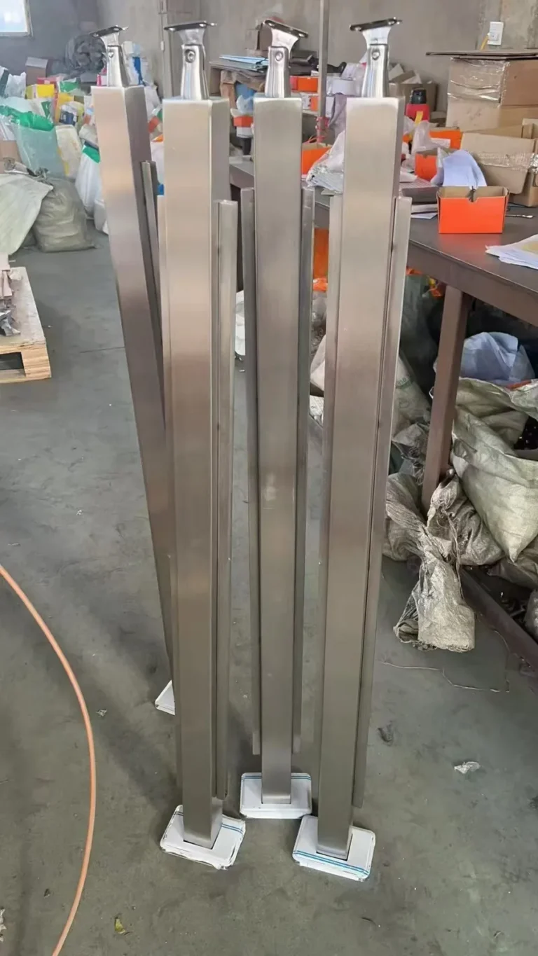
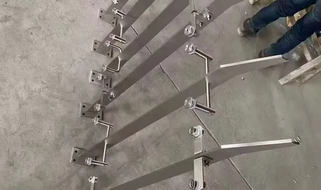
Short answer: choose a stainless steel railing post base plate from the project load path, mounting direction, substrate, anchor design, post geometry, corrosion environment and installation access—not from appearance alone. The structural plate, welds and anchors must be engineered together. A cover plate normally hides the connection and protects the visual finish; it should never be assumed to add structural capacity unless the approved design says so.
This product guide helps overseas buyers, railing distributors and project teams define top-mounted and fascia-mounted stainless steel baluster post connection components before requesting a quotation.
What is the difference between a base plate and a cover plate?
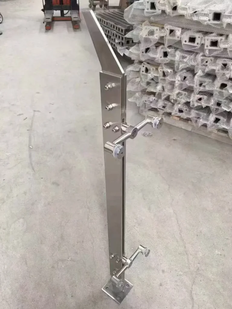
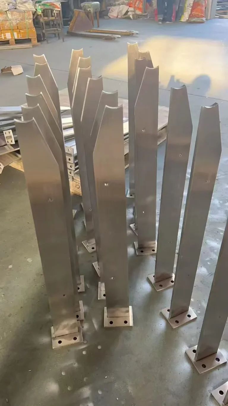
A base plate is the structural interface between a railing post and its supporting construction. It may be welded to a square tube, round tube or flat-bar post, or form part of a bolted post assembly. Its geometry transfers forces from the post into anchors and then into the substrate.
A cover plate, escutcheon or flange cover is generally a non-structural trim piece. It can hide anchor heads, slots, shims, grout lines or the edge of a waterproofing detail. It also creates a cleaner transition between the post and finished floor. Unless the project drawing assigns it a structural function, do not count it in the connection capacity.
Which railing post mounting interface fits the project?
| Interface | Typical visual result | Coordination priorities |
|---|---|---|
| Exposed top base plate | Plate and anchors remain visible | Plate outline, holes, washers, drainage, finish and cleaning access |
| Top base plate with cover | Trim hides most connection hardware | Cover clearance, fixing method, finished-floor build-up and water path |
| Concealed or recessed interface | Minimal visible metal at floor | Pocket dimensions, waterproofing, tolerances, inspection and replacement access |
| Side or fascia bracket | Walking surface stays visually open | Slab edge, bracket offset, anchor access, edge trim and post orientation |
| Custom welded bracket | Adapted to steel, timber or concrete support | Approved detail, mating material, coatings, fasteners and installation sequence |
The earlier railing post mounting methods guide compares top, side, fascia and embedded concepts. This article goes one level deeper: how to define the plate, bracket and cover that make the chosen concept manufacturable and inspectable.
Why there is no universal railing post base plate thickness
Base plate thickness cannot be selected from post height alone. The connection response depends on project loads, plate dimensions, post section, weld geometry, anchor layout, substrate condition, edge distance, eccentricity and installation tolerances. A thicker plate does not correct an unsuitable anchor pattern or weak supporting construction.
The American Institute of Steel Construction lists Design Guide 1, Base Connection Design for Steel Structures, as a current third-edition design resource. It illustrates that base plates and anchors belong to a connection system. It is not a railing-specific design approval, and project requirements must be established by the responsible engineer and applicable authority.
For purchasing, request the approved plate thickness and dimensions rather than asking a supplier to choose a “standard” size without design inputs. If value engineering is invited, keep the proposed alternative separate until it receives technical approval.
What dimensions belong on the fabrication drawing?
A reviewable base-plate drawing should define the connection from stable datums. At minimum, show:
- Post type, section dimensions and orientation.
- Plate length, width, thickness and corner shape.
- Hole or slot quantity, size, centre locations and orientation.
- Post-to-plate position, including any intentional offset.
- Weld location and the project-approved weld requirement.
- Visible faces, edge treatment and surface-finish direction.
- Cover plate outline, height, internal clearance and retention method.
- Finished-floor level, grout or shim zone and waterproofing interface.
- Left/right, stair, corner or fascia variants.
Dimension the plate and post from the same coordinate system used by the site layout. A correct part can still be impossible to install when the drawing omits slab edges, upstands, nosings, façade zones or tool clearance.
Which stainless steel product form should be specified?
State the required stainless grade for the plate, post body and welded components. Do not use “stainless steel” as a complete material description. The current ASTM A240/A240M-26 page covers chromium and chromium-nickel stainless steel plate, sheet and strip for general applications, including architectural and construction uses. A material standard identifies the product basis; it does not determine the finished railing connection.
SUS304/304L and SUS316/316L selections must follow the project environment and specification. If the post, base plate, anchors or nearby metal use different grades or materials, identify each one in the bill of materials. Avoid silently pricing a lower grade for a hidden plate.
How should the base plate finish match the post?
Define whether the plate top, exposed edges and weld zone must match the post’s brushed, satin, mirror or decorative finish. Also specify grain direction on visible faces. A plate cut from prefinished sheet may still require edge finishing and restoration after welding.
Post-weld appearance should be assessed after the required cleaning and blending process, without hiding fabrication defects or rounding critical geometry. The weld finishing and inspection guide separates structural fabrication acceptance from cosmetic finish matching.
How do anchors and the substrate affect plate selection?
The post manufacturer should not choose anchors from the stainless plate drawing alone. Anchor type, diameter, embedment, spacing, edge distance and installation procedure depend on the substrate, loads, environmental exposure and governing design method. Concrete, structural steel, masonry and timber require different connection strategies.
Provide the engineer-approved anchor specification or clearly mark anchors as by others. Confirm whether the supplier scope includes holes only, anchors and washers, templates, or a complete coordinated package. When anchors are supplied separately, the plate hole geometry still needs to match the approved system.
Slots may help field adjustment but change how washers, bearing and appearance are coordinated. Oversized holes are not a substitute for accurate survey information. Any change in hole size, slot direction or anchor position requires design review.
What installation access should be checked?
Model the installer’s real sequence. Check whether a drill, socket, torque tool and inspection equipment can reach every anchor. Allow for the post body, glass adapters, handrail brackets, slab edges and adjacent finished surfaces. A cover plate must pass over the post or assemble around it in the intended order.
For fascia mounts, show the distance from the post centreline to the slab face and finished edge. Confirm whether the bracket conflicts with façade panels, drip edges, waterproofing or reinforcement zones. For stairs, identify left- and right-hand variants and the relationship between the plate, tread nosing and sloping handrail.
How should water and dissimilar metals be managed?
A horizontal cover can trap moisture and debris around the post if drainage and sealing are not coordinated. Define whether the project uses a drained, sealed or otherwise protected interface, and ensure that the choice is compatible with the substrate and waterproofing system. Avoid creating a concealed wet crevice that cannot be inspected.
The British Stainless Steel Association explains that bimetallic corrosion requires dissimilar metals in electrical contact plus a conductive liquid. Exposure, relative areas and the material pairing affect risk. Where stainless steel meets aluminium, galvanized steel or another metal, the project team should specify compatible isolation, coating or moisture-control details rather than relying on a generic washer note.
When is a cover plate useful—and when is it not?
A cover plate is useful when the design needs a consistent architectural transition, concealed anchor heads or a replaceable finish component. It can also allow the structural plate to use practical holes and washers while presenting a cleaner visible outline.
A cover is not a remedy for poor welds, mislocated anchors, excessive gaps, inadequate corrosion detailing or an unapproved base connection. It should remain removable when future inspection or tightening is required. If it is bonded or sealed permanently, confirm the maintenance and replacement plan.
What should be approved before batch production?
For custom posts, approve a drawing and, when appropriate, a physical first article or finish sample. Check the actual post-to-plate angle, hole pattern, plate flatness, weld appearance, finish direction, cover fit and installation access. Record approved deviations rather than relying on photographs alone.
Batch inspection can then verify the defined characteristics using the agreed sampling plan. Protect finished plates and covers from post-to-post contact during export packing. Loose covers, anchors or templates should be labelled so installers can match them to the correct post type and location.
Base plate and cover plate RFQ checklist
- Released railing-post and connection drawings with revision numbers.
- Quantity by straight, corner, end, stair, left/right and fascia variant.
- Stainless grade and product form for every plate and post component.
- Plate dimensions, thickness, holes, slots, offsets and edge treatment.
- Engineer-approved anchor system or a clear “anchors by others” note.
- Substrate, slab-edge, finished-floor and waterproofing information.
- Weld, finish, grain direction and visible-face requirements.
- Cover geometry, retention, removability and drainage or sealing intent.
- Inspection records, first-article approval and packaging requirements.
- Included/excluded component schedule for quotation comparison.
Use this component schedule with the broader OEM stainless steel railing post RFQ checklist. A clearly defined base connection reduces quotation assumptions and makes supplier answers comparable.
How BalusterPost handles custom post interfaces
BalusterPost focuses on drawing-based stainless steel baluster posts and stainless steel railing posts, coordinated from Taizhou, Jiangsu, China. A core post such as the square tube glass balustrade post can be manufactured to an approved connection drawing. Separate base-plate hardware may also be coordinated through qualified specialist manufacturing resources when requested; its source and scope should remain explicit.
The site’s balustrade post base plate page shows a related connection component, not a universal engineered solution for every railing. Send Ryan Liang, Export Manager, the post schedule, substrate details and approved connection drawing for a quotation review.
Frequently asked questions
How thick should a stainless steel railing post base plate be?
There is no universal thickness. The responsible engineer must consider the project loads, plate size, post section, welds, anchor layout, substrate, edge distance and installation tolerances.
Is a railing post cover plate structural?
Usually it is architectural trim that hides the structural plate and anchors. Do not assign it structural capacity unless that role appears in the approved design.
Should a railing post base plate use 304 or 316L stainless steel?
Use the grade required by the project environment and specification. Identify the grade separately for the post, plate, welded components, anchors and nearby dissimilar materials.
Can the post supplier select the anchors?
Only when the contract assigns that design responsibility and supplies the necessary loads, substrate and code criteria. Otherwise provide the engineer-approved anchor system or mark anchors as by others.
What information is needed to quote a custom base plate?
Provide the released drawing, post variants and quantities, plate geometry, material, finish, anchor responsibility, substrate interface, cover details, inspection scope and packaging requirements.